
Georeferencing: One Point
To access this function:
-
Activate the Georeference ribbon and select One Point.
Note: Georeferencing isn't relevant to level or wireframe maps, which always have a world coordinate context.
Studio Mapper presents a collection of map data objects, known as a "Map". A map can contain a variety of artefacts including a drive profile, image, contact and polygon strings, structures and so on. A map can represent a single face or a full or partial drive. This can be determined interactively as well as being predefined with Studio Mapper's System Configuration File.
Initially, a map is generated without any reference to its position in world coordinates. This "local map" is displayed using a dedicated map window that would generally be used in a 2D sense to digitize geological features and otherwise embellish the map with useful information. Studio Mapper presents this information using a dedicated "Map view". The Map view can be used both before and after georeferencing to manage the contents of a map with regards to features, comments, sketches and so on.
A map is georeferenced to position it in 3D world space.
Studio Mapper's simplest georeferencing method is the "1 point method". It relies on the definition of a landmark position on the map which is translated to world coordinates. In Studio Mapper, this can be done interactively, using the 3D World view.
Once a map is georeferenced, you can continue to add features to it using the Mapping task bar and a local map window; as the same map is shown in the 3D World view, any changes are automatically reflected there also. It is generally recommended to create and edit geological elements of a map using the local map window, using the 3D World view to visualize the mapped faces in their true world positions, for example, aligned with an imported mine layout design file.
Notes:
- You can re-georeference a map in the 3D window using any of Studio Mapper's georeference methods. In this situation, your control points can be picked in either the 3D or map view.
- When a map is georeferenced, the associated image file(s) are used to generated a .jpgx file. This means, providing the .jpgx file is in the same location as the image file, you can drag/drop the images into any Studio product's 3D window, and the image wireframes will be constructed at the correct world coordinates.
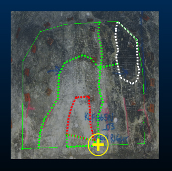
For example, the images below show two local face maps in their own local coordinate system. A few features have been digitized. Each has been georeferenced using the One Point option on the Georeference ribbon. On each map, the anchor point is shown as a yellow crosshair. Map 1:
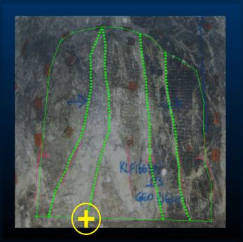
Map 2:
The second point (for each map) is picked in the 3D World view. In this case, each map's anchor point is translated to a snap point on a (red) drive design string:
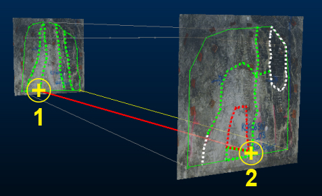
Subsequent edits to either map will now be represented in both the local map and 3D World view.
You then define the orientation of the map around this anchor point using the Rotate function (also on the Georeference ribbon), which provides an on-screen controller to adjust the orientation of the map in any of the 3 major axes, for example:
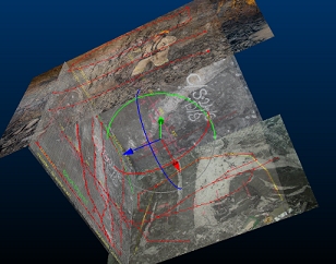
Rotation repositions the map in 3D space, and can be performed in either a 3D World view or a Map view (both georeferenced and local maps can be rotated).
Related topics and activities